← All chapters
Driving Manual · Theory

Chapter 13 - Traction, Tires and Brakes

Traction, tyres, and brakes form the foundation of vehicle safety. Traction is the grip between tyres and road; tyres maintain that grip under varying conditions; brakes let the driver slow down or stop safely. Proper maintenance and understanding of these elements are essential for accident prevention.

Three-part illustration side by side: a tyre gripping a road surface (traction), a labelled tyre cross-section (tyres), and a brake disc with calliper (brakes)
Three pillars of vehicle safety: traction, tyres, and brakes.

13.1 Introduction

Traction, tyres, and brakes form the foundation of vehicle safety. Traction refers to the grip between the tyres and the road, while tyres ensure that this grip is maintained under various conditions. Brakes allow the driver to slow down or stop safely. Proper maintenance and understanding of these elements are essential for accident prevention.

A simple flow diagram showing the relationship between the three components: tyre to road contact patch to braking force, with arrows linking each stage
Tyre grip creates the road contact that makes braking force possible - all three are interdependent.

13.2 Vehicle Traction

13.2.1 What is Traction?

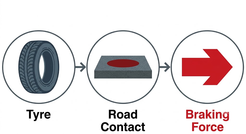
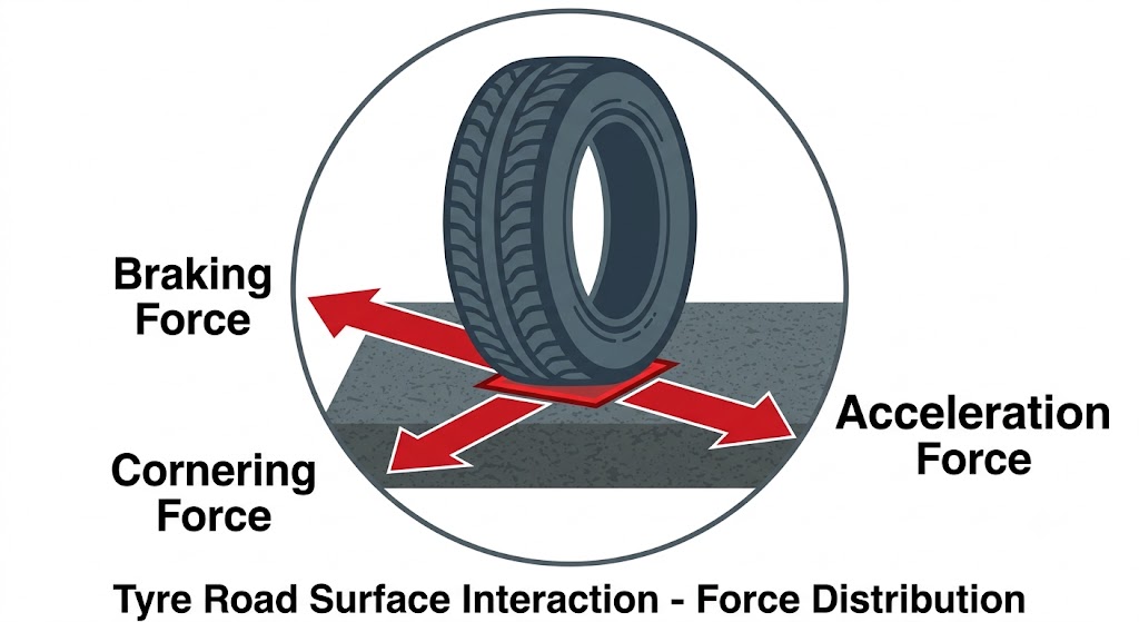
Traction is the force that allows the vehicle's tyres to grip the road surface. It is necessary for accelerating, braking, and steering. The level of traction varies with road condition, tyre type, weather, and vehicle load.

Top-down and side diagram of a tyre touching the road surface, showing the contact patch with force arrows indicating grip during acceleration (forward), braking (rearward), and cornering (lateral)
The contact patch - the small area where tyre meets road - is where all traction forces act.

13.2.2 Factors Affecting Traction

  • Road surface: wet, icy, or gravel roads reduce traction.
  • Tyre condition and pressure: worn-out or underinflated tyres decrease grip.
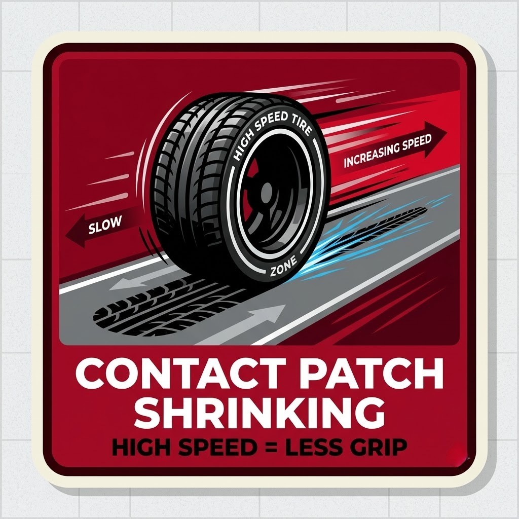
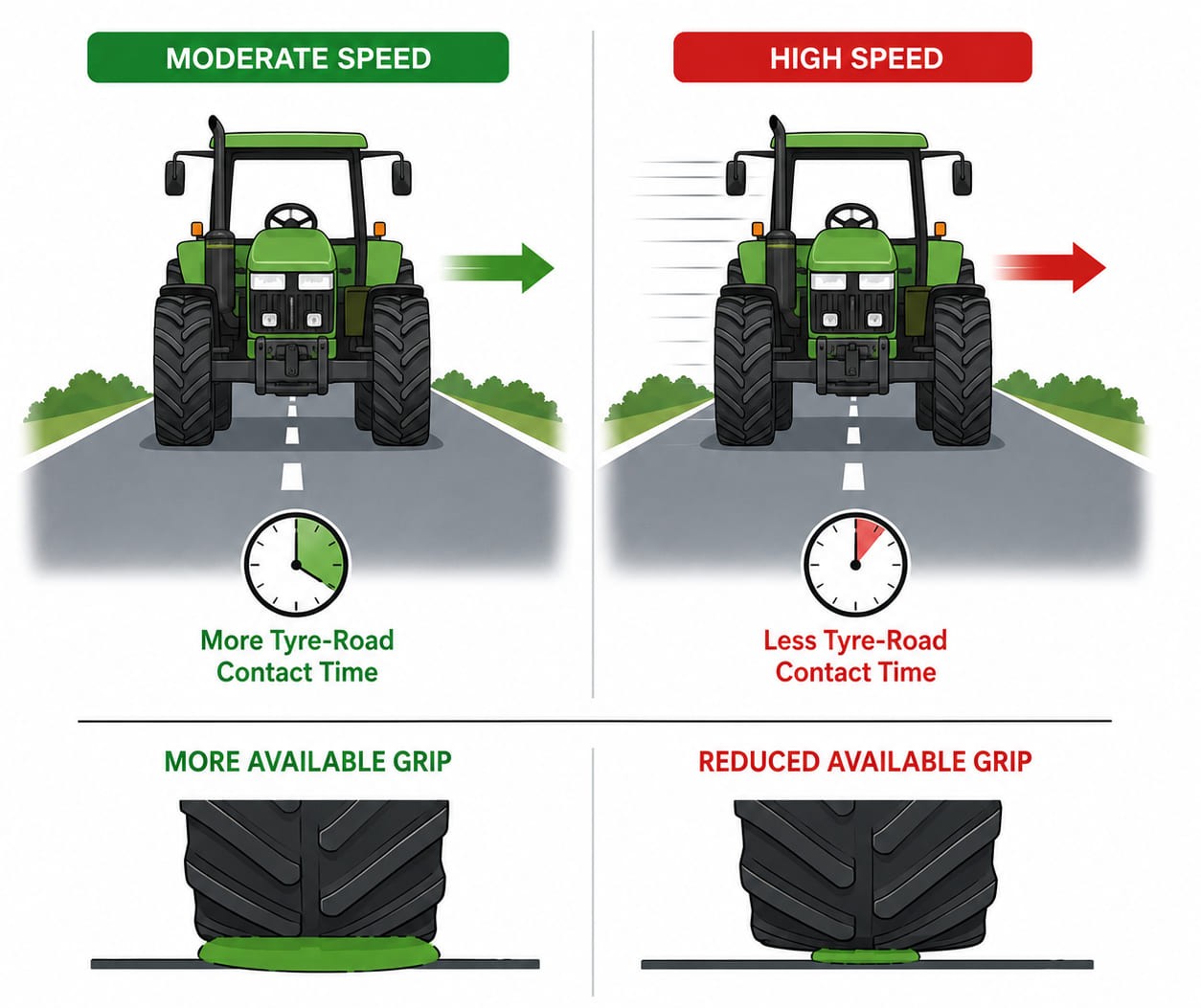
  • Vehicle speed: higher speeds reduce tyre-road contact time.
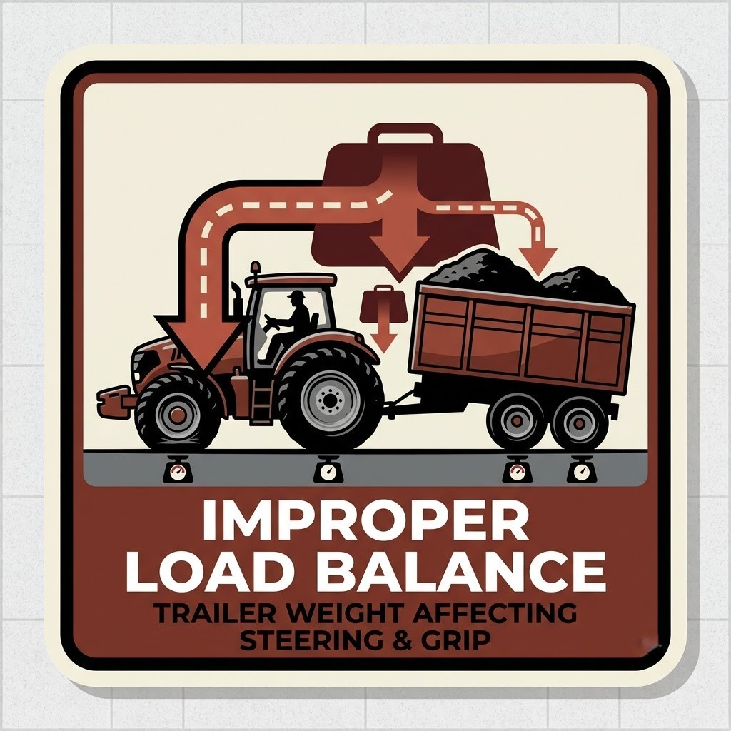
  • Load: an overloaded vehicle alters weight distribution and traction.
A wet or icy road surface icon showing reduced grip, with water or ice crystals on tarmac
Road surface
A worn-smooth tyre cross-section with minimal tread depth, contrasted with a new tyre
Tyre condition
A speedometer showing high speed with a reduced tyre-road contact time indicator
Vehicle speed
An overloaded car with suspension compressed, showing altered weight distribution
Vehicle load

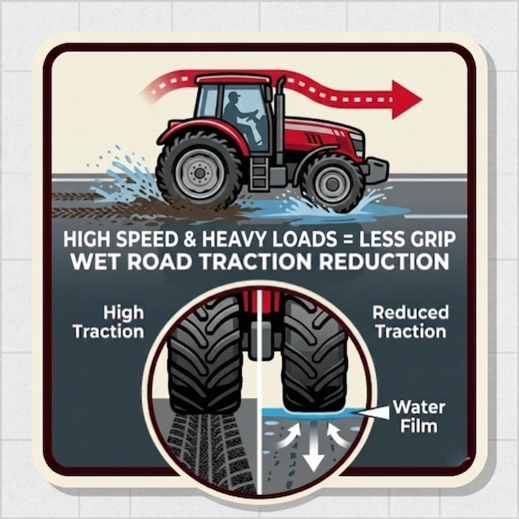
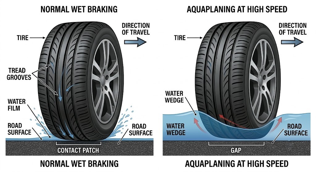
13.2.3 Loss of Traction: Aquaplaning

Aquaplaning occurs when a layer of water causes tyres to lose contact with the road. The vehicle skids and becomes unresponsive to steering or braking. Risk increases at high speeds, with wide or worn tyres, and low pressure. Prevention: reduce speed during rain, and ensure proper tyre pressure and tread depth.
Two-panel cross-section diagram: left panel shows a tyre with good tread on dry road, full contact patch visible; right panel shows the same tyre on a water layer, lifted clear of the road surface with a "no contact" label. A secondary panel shows prevention: adequate tread depth and correct tyre pressure.
Aquaplaning: water lifts the tyre off the road - steering and braking become impossible.

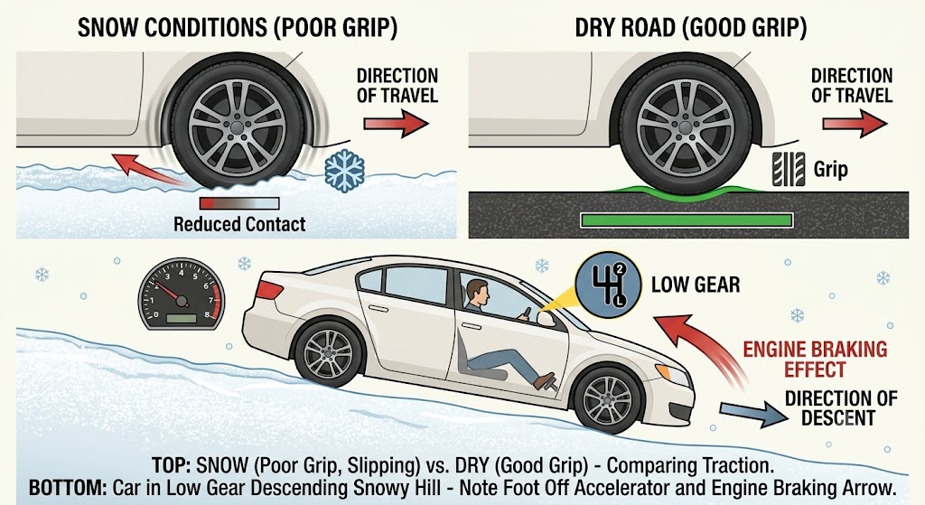
13.2.4 Traction on Snow and Ice

  • Use snow chains or winter tyres.
  • Accelerate and brake gently. Use high gears to avoid wheelspin.
  • Descend hills in low gears, using engine braking.
  • Avoid sudden manoeuvres or abrupt braking.
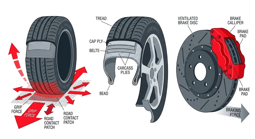
Split image: left shows a summer tyre on a snowy road with poor grip; right shows a winter tyre and snow chains on the same road with markedly better contact. Below, a side diagram shows a car descending a hill with engine braking engaged in a low gear.
Winter tyres and snow chains dramatically improve traction - always descend snowy hills in low gear.

13.3 Tyres

Vehicle wheels are made up of two parts:

RimThe circular metal piece that forms the inner part of the wheel.
TyreThe elastic rubber piece fitted around the rim.
A labelled cross-section diagram of a complete wheel, with clear arrows pointing to the rim (metal inner structure) and the tyre (rubber outer layer), plus sub-labels for sidewall, bead, and tread
A wheel = rim (metal) + tyre (rubber) - each has a distinct role.

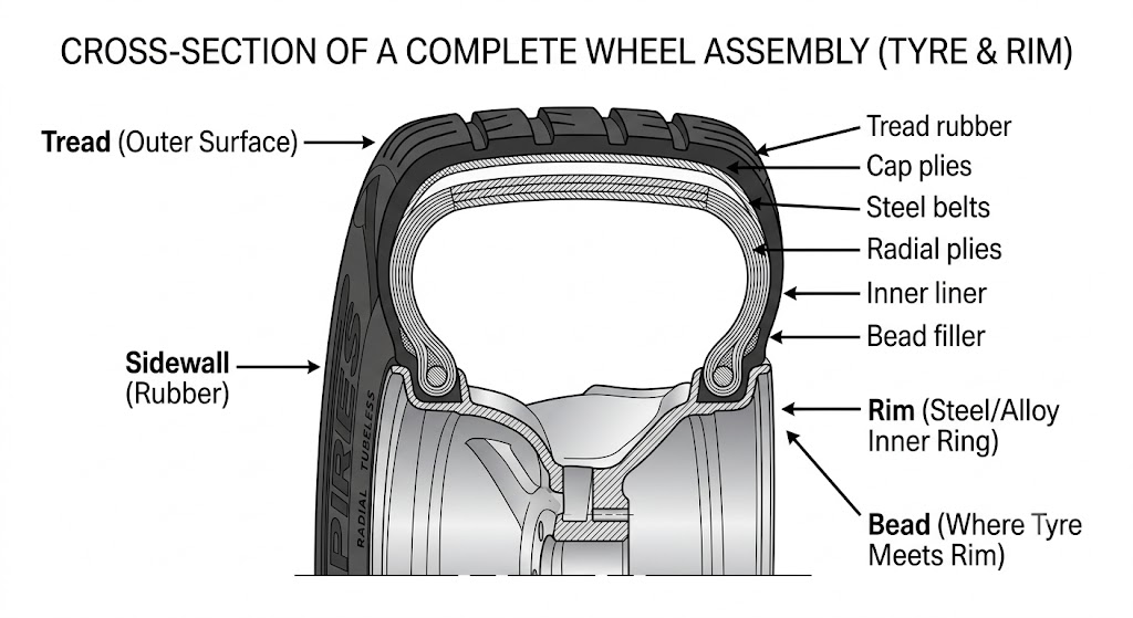
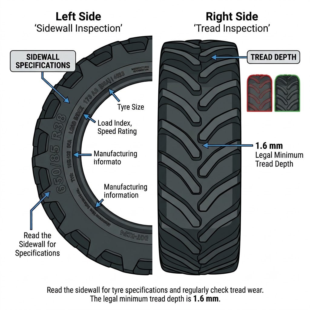
Tyre failures are a common cause of traffic accidents, so it is very important they meet proper quality standards. On new or good-condition tyres, specifications can be read on the sidewall. They must not have bulges, deformities, or cuts; no layers should be coming loose; and there should be no exposed cables or cracks.

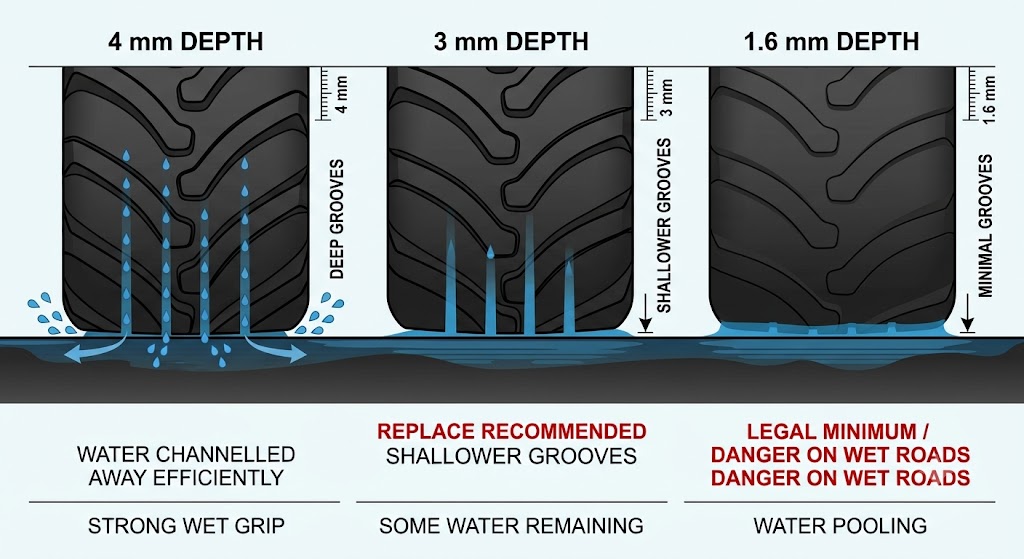
The part of the tyre in contact with the road is the tread. For passenger cars, the tread must have grooves at least 1.6 mm deep. These grooves allow the tyre to:

  • Avoid overheating.
  • Be more flexible and roll more smoothly.
  • Grip the road surface better.
  • Expel water collected from the road when it rains.
Two-part illustration: left shows a tyre sidewall with the specification stamps highlighted (size, load index, speed rating); right shows a tread cross-section with grooves labelled for water expulsion, heat dissipation, and grip. A tread depth gauge showing the 1.6 mm minimum marker is included.
Read the sidewall for specs; check the tread for wear - 1.6 mm is the legal minimum depth.

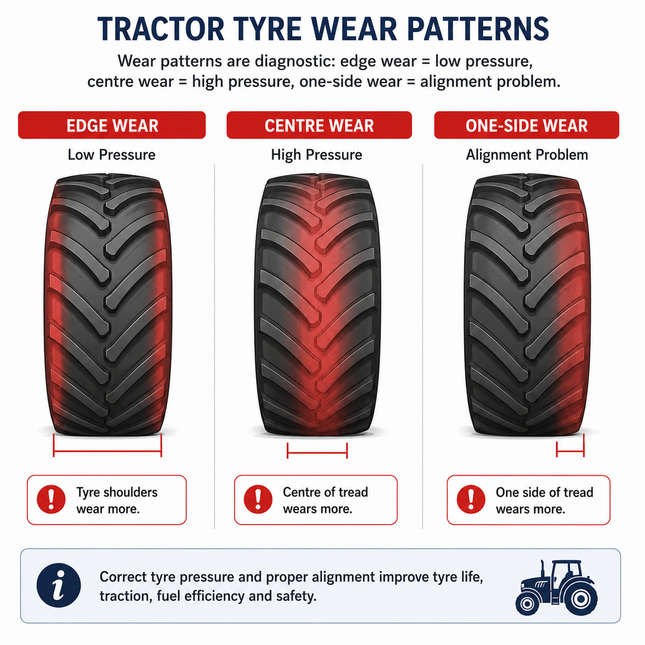
13.3.1 Tyre Pressure

The manufacturer determines the correct amount of air each tyre should have - the inflation pressure. Check pressure when tyres are cold, at least once a month. Always carry a spare wheel at the correct (maximum recommended) pressure if possible. Incorrect pressure causes uneven wear, poor grip, and higher fuel consumption.

Pressure lower than recommended The tyre heats up, deforms, and wears faster; the vehicle uses more fuel; it becomes less stable; higher risk of skidding on wet roads; increased chance of a blowout.
Pressure higher than recommended Less contact with the road, so grip is reduced; the vehicle vibrates more (absorbs stones/defects less); shock absorbers wear faster; the centre of the tread wears faster than the shoulders.
Three-panel tyre cross-section diagram: left - underinflated tyre bulging at the shoulders with excessive edge contact and deformation; centre - correctly inflated tyre with even contact patch; right - overinflated tyre convex in shape with only the centre tread touching the road. Wear pattern strips beneath each panel show the resulting tread wear.
Pressure too low: shoulder wear and blowout risk. Pressure too high: centre wear and reduced grip.

13.3.2 Tread Depth

  • Legal minimum: 1.6 mm.
  • Recommended: replace when below 3 mm for safety, especially in wet conditions.
Three side-by-side tyre tread cross-sections on a wet road surface: left - 4 mm depth (good, water channelled away effectively); centre - 3 mm (replace recommended, reduced water expulsion); right - 1.6 mm (legal minimum / worn, poor wet grip). Labels and depth markers for each stage.
Replace at 3 mm - at 1.6 mm (legal minimum) wet-road grip is seriously degraded.

13.3.3 Tyre Maintenance

  • Check for cracks, cuts, bulges, or foreign objects.
  • Replace all four tyres, or at least both on the same axle, with the same type, size, and category.
  • Avoid mixing tyres of different types (radial/bias) or seasons (summer/winter).

Tyre wear. Rubber wears down due to friction with the road, so replace tyres every five years even if they appear to be in good condition.

Causes of premature wear:

  • Harsh or aggressive driving.
  • Very high speeds.
  • Weather conditions - tyres wear more in summer.
  • Heavy loads carried by the vehicle.
  • Incorrect inflation pressure.
  • Poor road conditions.
  • Brake issues or other vehicle faults affecting the wheels.
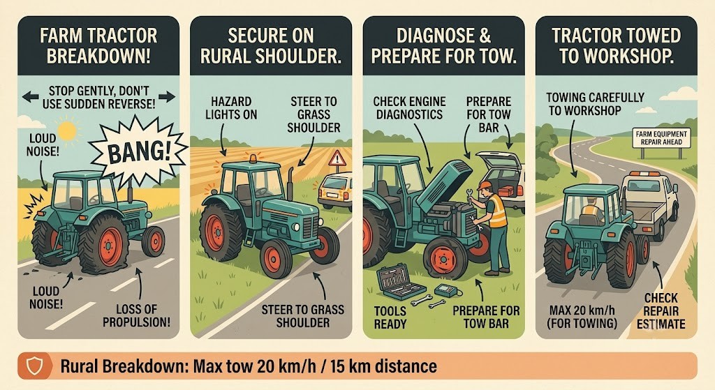
A wear pattern chart showing three tyre tread views from above: (1) edge wear on both shoulders - indicates underinflation; (2) centre wear - indicates overinflation; (3) one-sided wear - indicates alignment or camber issue. Each pattern is labelled with its cause.
Wear patterns are diagnostic: edge wear = low pressure, centre wear = high pressure, one-side wear = alignment problem.

13.3.4 Tyre Blowout

In case of a sudden blowout:

  • Hold the steering wheel firmly.
  • Do not brake suddenly; decelerate gradually.
  • Pull off the road and stop safely.
If you get a flat tyre while driving:
  • Slow down gradually until you stop. Do not brake sharply.
  • Secure the vehicle in a safe place, preferably off the road and hard shoulder.
  • Replace the flat with the spare. Some vehicles have alternative systems allowing limited driving, and some carry a space-saver spare intended only to reach a nearby workshop.
  • You can typically drive on a space-saver spare for up to 200 km at a maximum of 80 km/h.
A four-step illustrated sequence for tyre blowout response: step 1 - blowout shown with burst tyre; step 2 - driver gripping steering wheel firmly with both hands; step 3 - gradual deceleration arrow (no brake pedal); step 4 - car pulled safely onto the shoulder and stopped. A small info badge shows the space-saver rule: 200 km max / 80 km/h max.
Blowout: grip firmly, decelerate gradually, pull over - never brake hard.

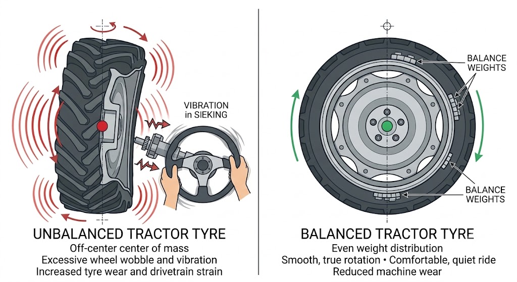
13.3.5 Wheel Balancing

Wheel balancing consists of adding weights to the rims so the wheels properly support the vehicle's weight and load. This balance is essential for the wheels to rotate smoothly. Wheels can become unbalanced due to:

  • Tyre replacement.
  • Loss of wheel weights.
  • Dented or damaged rims.
  • Tyre wear or cuts.

How to tell a wheel is out of balance: noise and vibration from the vehicle, excessive or abnormal tyre wear, and loose wheel nuts.

Two-panel diagram: left - an unbalanced wheel shown wobbling off-axis during rotation, with vibration lines radiating outward; right - a balanced wheel with small weights attached to the rim, rotating smoothly. A secondary inset shows a steering wheel vibrating vs. steady to illustrate the symptom.
An unbalanced wheel wobbles and vibrates - small balance weights on the rim restore smooth rotation.

13.4 Brakes

The brakes reduce the vehicle's speed until it comes to a complete stop. Braking systems rarely fail, but when they do it may cause a serious accident.

13.4.1 Types of Brakes

Service brakeFoot brake system acting on all wheels.
Emergency brakeActivates part of the main brake circuit if the service brake fails.
Parking brakeHand-operated, used to immobilise the vehicle.
A top-down or side view of a car with three brake systems highlighted in different colours: service brake (blue) - foot pedal connected to all four wheels; emergency brake (amber) - partial circuit; parking brake (red) - handbrake lever at rear wheels. Each is labelled.
Three brake systems: service (all wheels), emergency (partial circuit), and parking (handbrake).

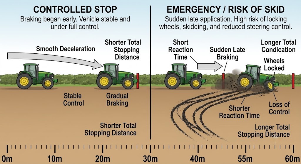
13.4.2 How to Brake Properly

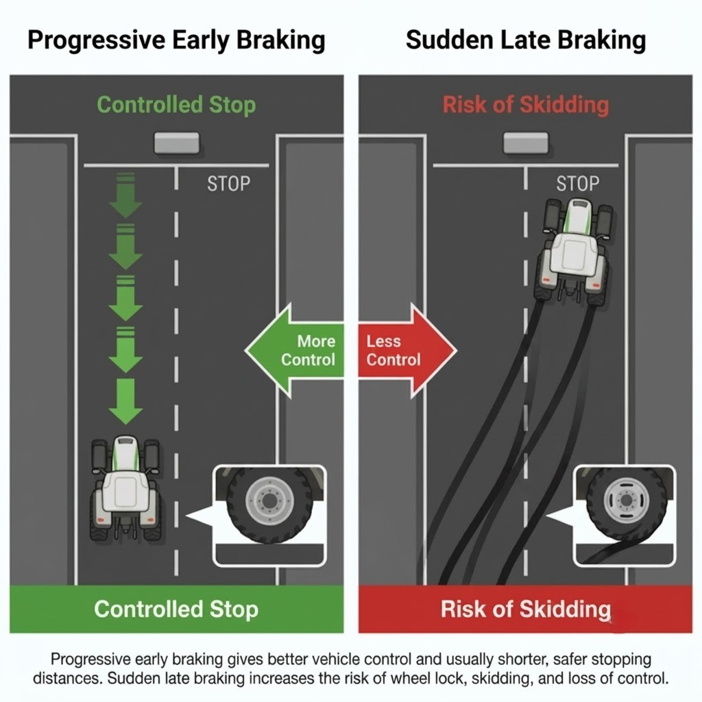
  • Brake progressively and early to reduce wear and avoid abrupt stops.
  • Use engine braking (downshifting) on long descents.
  • In case of emergency braking with ABS: press the pedal firmly and do not release it.
A side-by-side stopping distance diagram: left - progressive early braking showing a long, controlled deceleration arrow with full steering maintained; right - sudden late braking showing a shorter but uncontrolled stop with wheel-lock marks. Distance labels show the difference.
Progressive early braking gives control and shorter distances - sudden late braking risks skidding.

13.4.3 Brake Safety Systems
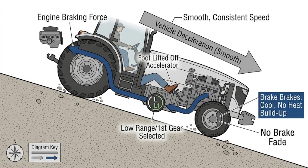
Engine Braking

Reduces speed without using the wheel brakes - it works when you release the accelerator, so the engine holds the vehicle back. In lower gears (1st or 2nd) the braking effect is greater. Recommended on long downhill stretches.

A side-view diagram of a car descending a steep slope. The accelerator pedal is shown released, with an arrow from the engine back through the drivetrain showing the restraining force. Gear indicator shows a low gear selected. Label: "engine braking - no heat build-up in brake pads".
Engine braking on descents protects your brakes from overheating - stay in a low gear.

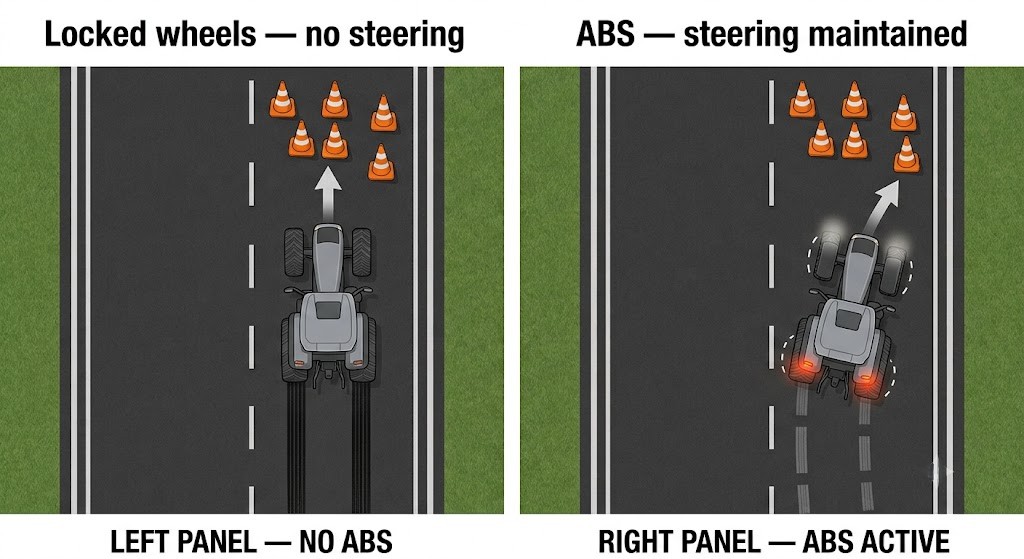
ABS - Anti-lock Braking System

Prevents the wheels from locking during emergency braking, preserving steering control. Press the pedal firmly and hold it. A vibration or noise may be felt - this is normal with ABS activation.

Two-panel top-down diagram: left - without ABS, wheels lock solid and the car slides straight, unable to steer around the obstacle; right - with ABS, wheels pulse and the car maintains steering control and swerves around the obstacle. Skid marks shown on the left, clean path on the right.
ABS prevents wheel lock - you keep steering control during emergency braking.

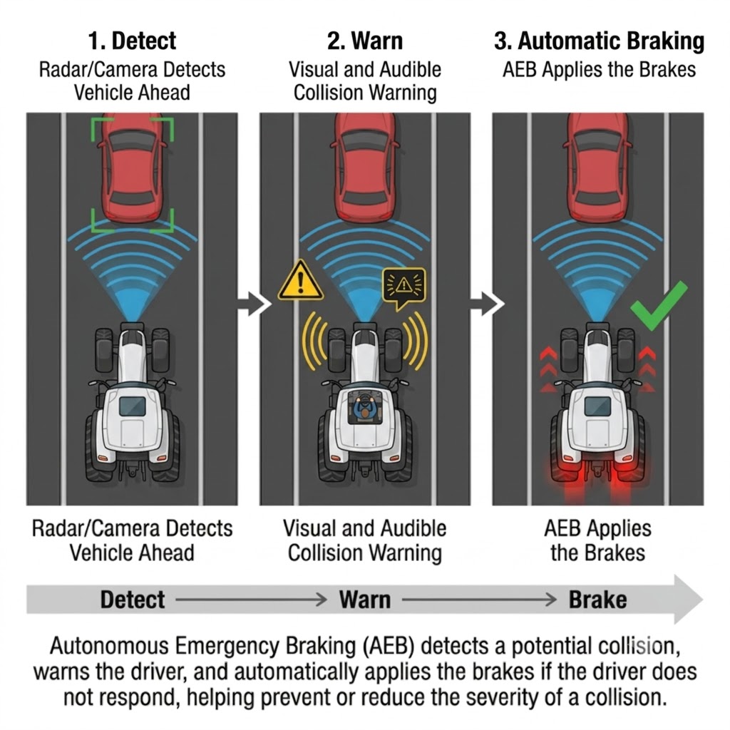
Autonomous Emergency Braking (AEB)

Uses a radar sensor to calculate the distance kept to the vehicle ahead. If the gap is too small, it warns the driver with audible/voice alerts; if the driver does not react and a collision is likely, it applies emergency braking to avoid or mitigate impact.

A three-stage top-down sequence: stage 1 - radar cone from the front of the car detects a slow vehicle ahead; stage 2 - warning icon and sound alert shown as the gap closes; stage 3 - automatic braking applied with deceleration arrows, avoiding a collision.
AEB detects, warns, then brakes automatically - three stages that can prevent a collision.

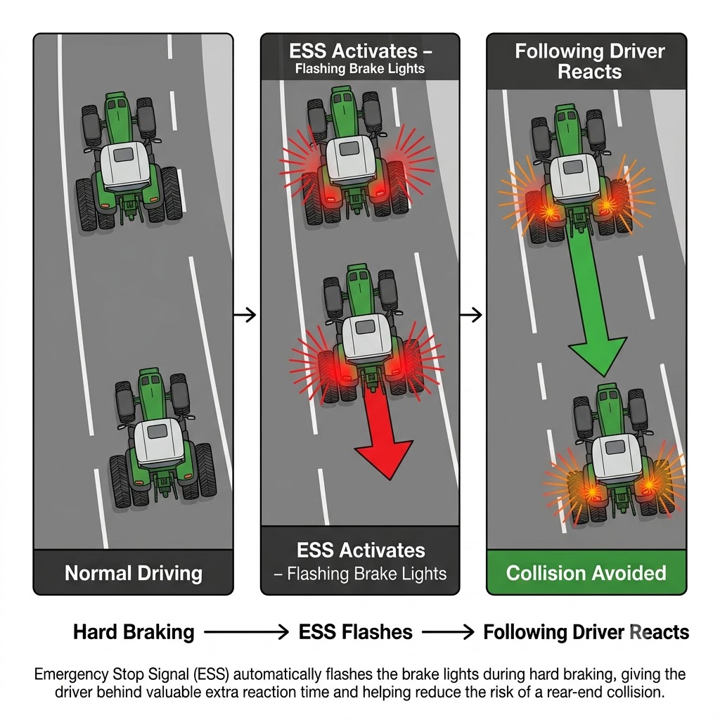
Emergency Brake Warning (ESS/EBD)

Alerts the following driver that the vehicle ahead must perform an emergency stop. On hard, quick braking the brake lights flash, giving the driver behind more time to brake. In some vehicles the hazard lights may also activate after hard braking.
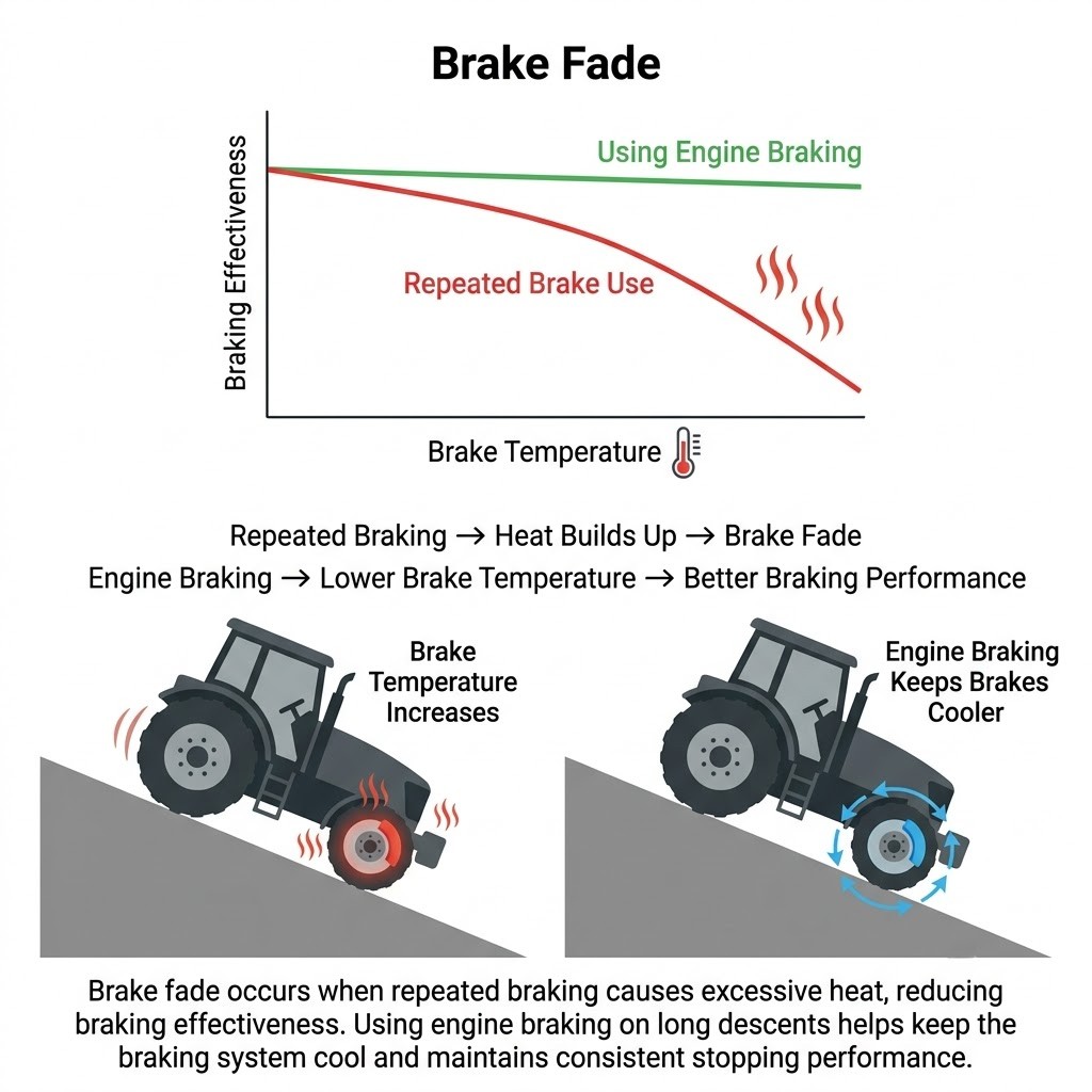
A rear-view diagram of a car braking hard, with brake lights shown flashing rapidly in a pulsing pattern. The following car behind has extra time to react, shown by a larger safety gap. A label reads: "ESS - brake lights flash during emergency braking".
ESS flashes the brake lights during hard braking - giving the driver behind vital extra reaction time.

13.4.4 Brake Fade

This happens when brakes overheat due to prolonged use (especially on slopes), reducing their effectiveness. Prevent it by using engine braking and avoiding prolonged foot-brake use.

A graph with temperature on the x-axis and braking effectiveness on the y-axis: the foot-brake line drops sharply as temperature rises on a long descent; the engine braking line remains flat and effective throughout. Labels mark the danger zone where brake fade occurs.
Brake fade: effectiveness drops as temperature rises - engine braking keeps the system cool.

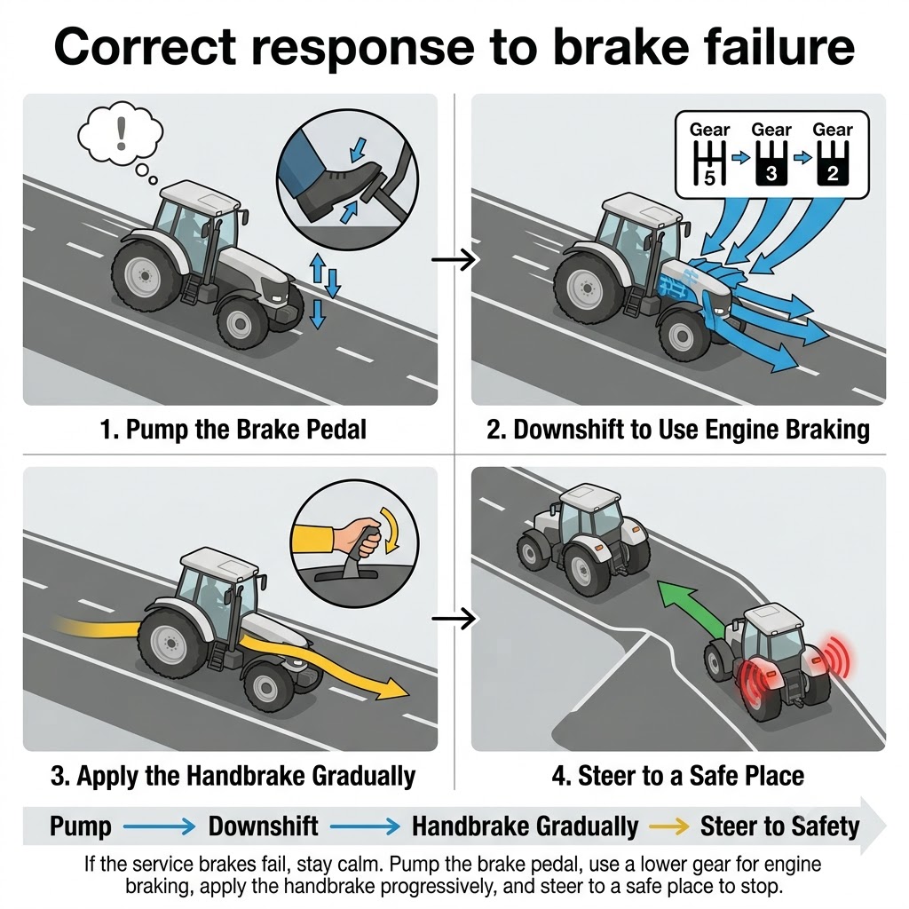
13.4.5 Brake Failure Response

  • Pump the pedal to activate residual pressure.
  • Use engine braking and reduce gear.
  • Apply the handbrake progressively if needed.
  • Steer towards an uphill road, soft barrier, or stop area.
A four-step illustrated emergency sequence for brake failure: step 1 - driver pumping the brake pedal repeatedly; step 2 - downshifting to a lower gear for engine braking; step 3 - handbrake handle being applied progressively; step 4 - car steered toward an uphill road or soft barrier to stop safely.
Brake failure response: pump, downshift, handbrake progressively, steer to safety.

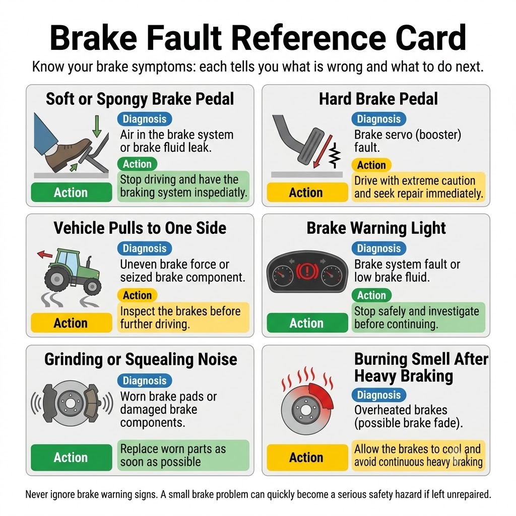
13.4.6 Common Brake Problems

SymptomPossible causeAction
Pedal sinksBrake fluid leakCheck fluid and system
Soft pedalAir in circuitBleed brakes
Hard pedalWorn padsReplace pads
Vehicle pulls to one sideUneven braking or pressureInspect system and tyres
A visual fault card with four cells, each showing a symptom icon and short label: (1) pedal sinking to the floor - fluid leak; (2) soft/spongy pedal - air in circuit; (3) stiff/hard pedal - worn pads; (4) car silhouette pulling left - uneven braking. Each cell has a colour-coded severity indicator.
Know your brake symptoms: each tells you what is wrong and what to do next.

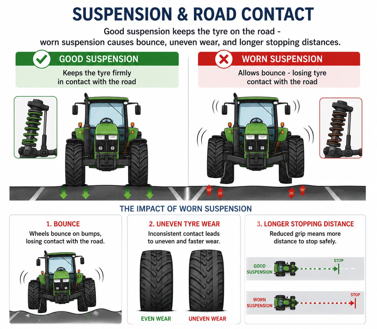
13.5 Suspension and Braking

The suspension maintains tyre-road contact. A faulty suspension increases braking distance and reduces control. Signs of wear: bouncing on bumps, uneven tyre wear, and drifting in curves. Have the suspension inspected during regular maintenance.

Two-panel diagram: left - good suspension with tyre flat on the road surface over a bump, contact patch fully maintained; right - worn suspension with tyre bouncing and lifting off the road on the same bump, reducing the contact patch to near zero. Secondary inset shows warning signs: bouncing arrow, uneven tyre wear strip, drifting curve arrow.
Good suspension keeps the tyre on the road - worn suspension causes bounce, uneven wear, and longer stopping distances.

13.6 Summary

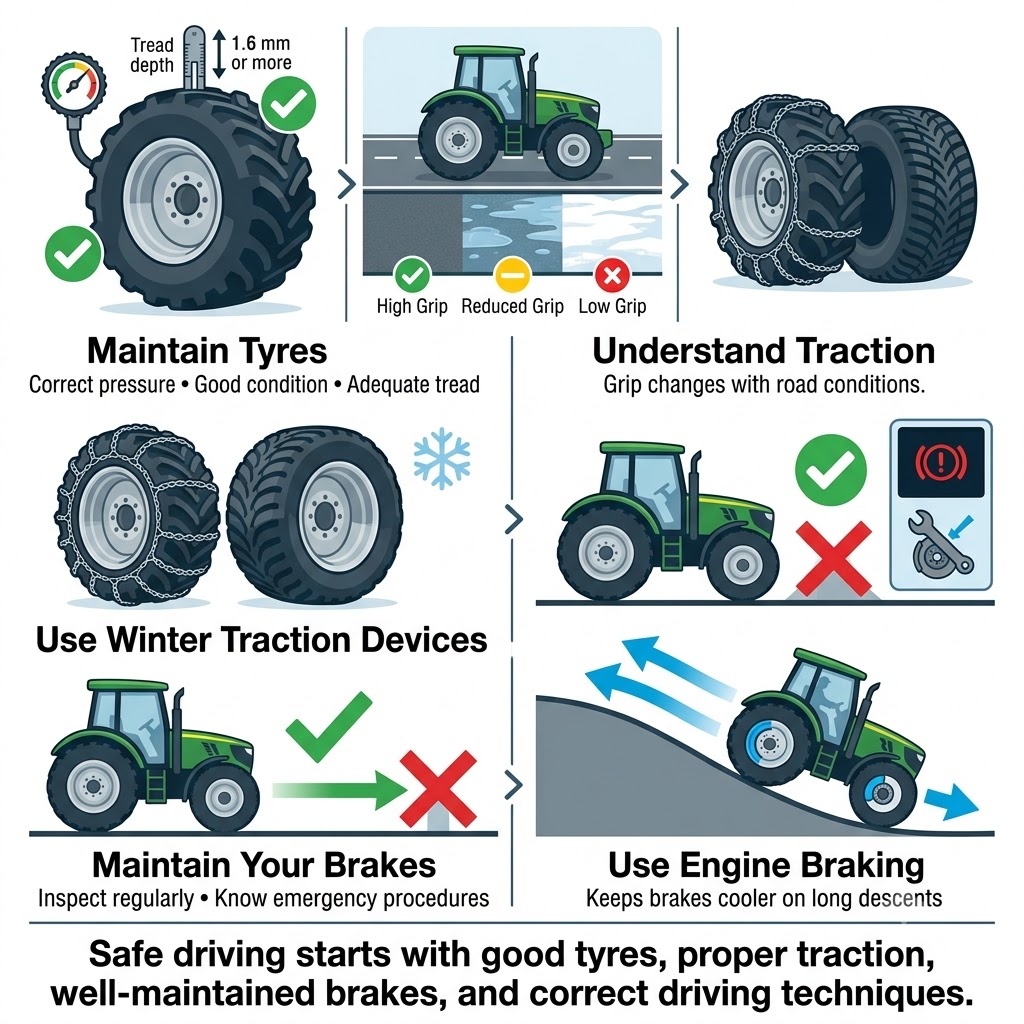
  • Ensure tyres are in good condition, with correct pressure and tread depth.
  • Understand how traction varies depending on the surface and conditions.
  • Use snow chains, winter tyres, or traction devices in adverse conditions.
  • Check brakes regularly and know how to respond in emergencies.
  • Use engine braking on long descents.
A horizontal five-icon recap strip: (1) tyre with a tread depth gauge - check pressure and tread; (2) road surface conditions icon - traction varies; (3) snow chain icon - use in adverse conditions; (4) brake disc - check brakes regularly; (5) gear shift lever - use engine braking on descents. Short label beneath each icon.
Chapter 13 at a glance: tyre condition, surface traction, winter equipment, brake checks, engine braking.

Ready to test your knowledge?

Practice questions covering everything in Chapter 13 - Traction, Tyres and Brakes.
Practice Chapter 13 →

Last updated: 2026-06-27

Practice the questions for this chapter

The theory is free to read. Create a free account to practice official-format questions and track your progress.